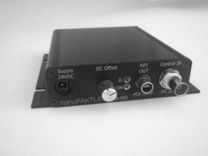
Description
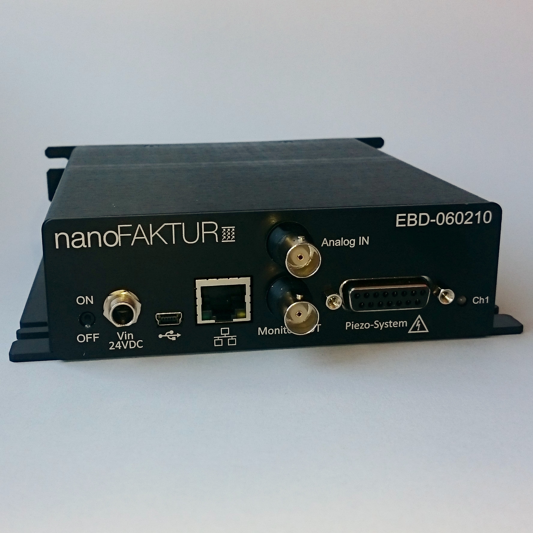
EBD-060 digital controllers provide closed-loop operation of piezo-systems. Such systems consist of low-voltage piezo-actuators combined with position sensors. EBD-060 control via full-bridge strain-gauge sensors. The nFControl Basic Software offers the ability to easily change control parameters via a Windows-based GUI. The controllers´ versatile enclosures allow for either simple integration into OEM equipment or table-top usage.
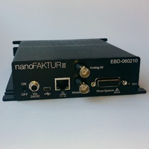
Single Channel Piezo Driver
| Product Code | EBD-060210 | Unit | |
|---|---|---|---|
| Channels | 1 | ||
| Output Voltage for Piezo | -45 to 180 | V | max. |
| Sensors | Strain Gauges (SGS) | ||
| Control Parameter | PID, 2 Notch Filters | ||
| Control Loop Time | 20 | µs | |
| Software | nFControl, Windows™ GUI | ||
| Operating System Requirements | Microsoft ® Windows™ 7/8/10 | ||
| Resolution | 18 bit | ||
| Data Recorders | up to 16 | ||
| Memory | 16M points for wave-/recorder -tables | ||
| Current | 150 peak, 60 average | mA | max. |
| Protection | Output: short circuit proof Supply: reverse polarity protected | ||
| Supply | 24 (2A max.) | Vdc | |
| Data Recorders | 2; 512 values each | ||
| Digital Interfaces | USB 2.0 (RS232 or Ethernet optional) | ||
| Analogue interfaces I/O | Input scalable in -10 to +10 V, Output fix -5 to +5 | V | |
| Connection, Piezo and Sensor | DSub15f | ||
| Connection, Analogue I/O | 2x BNC | ||
| Connection, P/S | Switchcraft RASPC10PS | ||
| P/S, counter-socket | Switchcraft Power Jack S10KS12 | ||
| Power supply | External, included | ||
| Ambient Temperature | +10 to +40 | °C | |
| Design | aluminium, Black | ||
| Dimensions, H x W x D | 41.5 x 130 (154 incl. shackles) x 157.5 (plus interfaces) | mm | |
| Standards | 2006/95/EC, Low Voltage Directive 2004/108/EC, EMC Directive 2011/65/EU, RoHS Safety (Low Voltage Directive): EN 61010-1:2010 EMC: EN 61326-1:2013 RoHS: EN 50581:2012 |
How do Controllers work?
Controllers for piezo-systems interact between actuators, sensors and users:
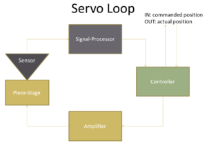
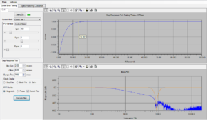
Digital controllers allow for easily adapting and optimizing control parameters (PID, notch-filters) and exchangability of connected mechanics (ID-Chip). Such controllers are typically equipped with analog and digital interfaces – USB, Ethernet and RS232. Graphical user interfaces (GUI) provide examination features like oscilloscope (view step-responses, rest-noise, etc.) and FFT (see Bode-Plots of amplitudes and phases over frequency).
Example, open loop:
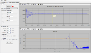
Closed-Loop with optimized parameters and notch-filter on the first resonance: