Description
Streak camera technology was developed for measuring ultra-fast optical phenomena. OptoScope streak cameras provide temporal resolution down to the Picosecond regime. Additionally, OptoScope systems have high sensitivity allowing single photon detection. Streak cameras are the only instruments that can capture the behavior over time of multiple optical signals. Combined with a spectrometer this allows their application in the field of time resolved spectroscopy.
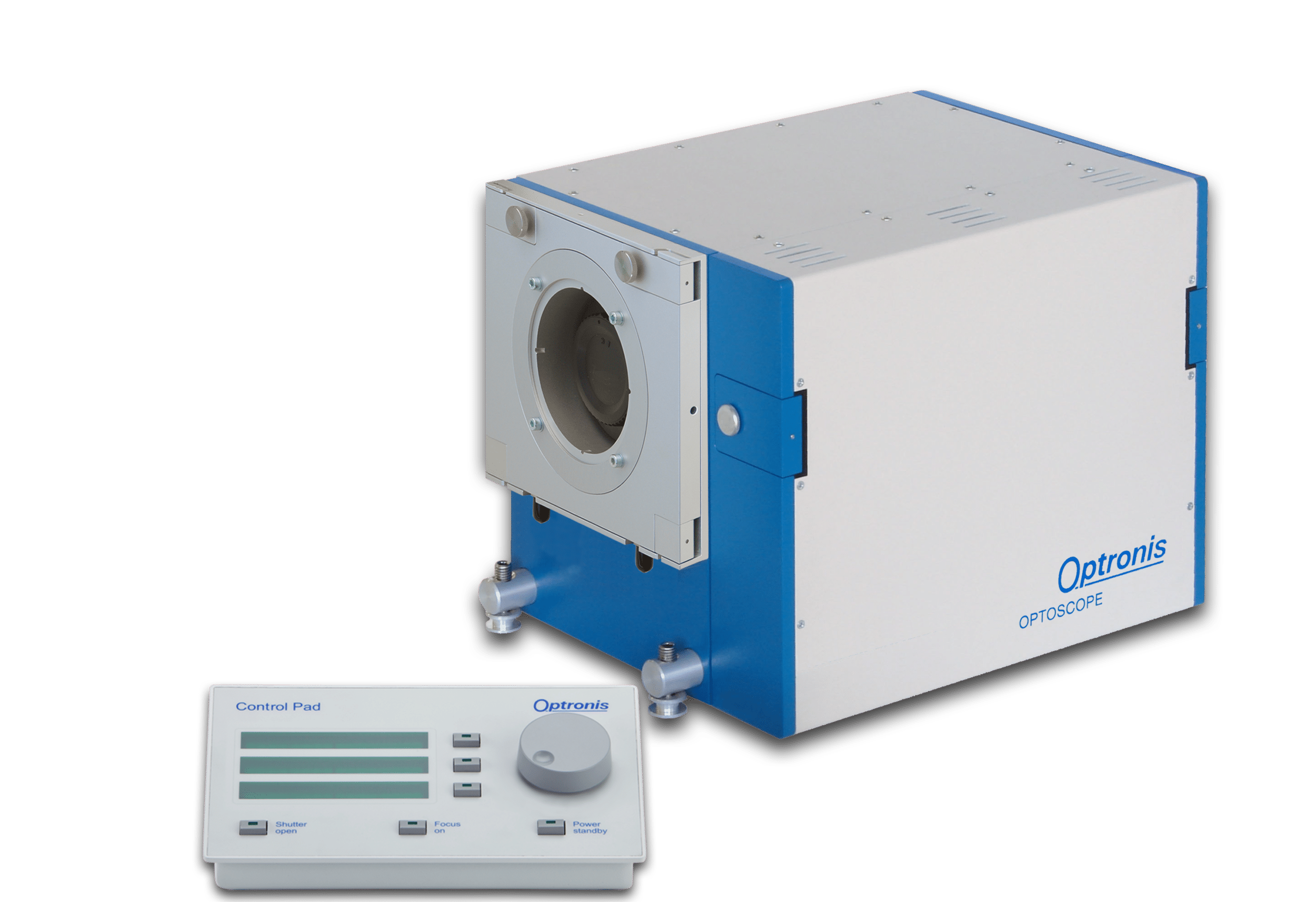
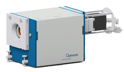
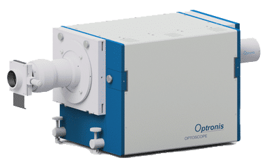
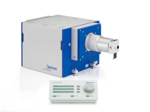
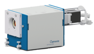
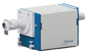
A SC-20 streak system consists of the main photocathode unit SC-20 with input optics, sweep unit and readout camera. Additionally, an image intensifier is optional. Adapt the spectral sensitivity to your application by selecting the photocathode type and input window version. Also, the photocathode includes a gating function as standard. The image intensifier and readout camera couples optically to the main unit via a fibre to obtain a compact system.
SC-20 Main Characteristics:
- Large detection area 35 mm
- Temporal res. <600 ps
- Trigger frequency 0…10 Hz
- Wavelength 230…950 nm
- High spatial resolution
- Triggered sweep
- High sweep linearity
- Fiberoptic input
- UV option
- Applications: Detonics and Plasma physics
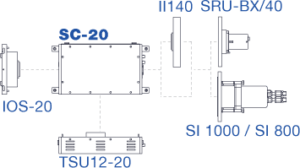
SC-20 System Overview:
Please see the Configurations tab for specifications of configurations.
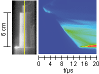
Detonation Velocity of Explosives
The article describes how a streak camera is used to measure the detonation velocity by observing the optical radiation emitted from an explosive compound. Detonation velocity is a key characteristic of explosives and describes the velocity a chemical reaction propagates through the material. During the explosion a slit image is streaked to provide temporal and spatial information. As sweep speed can be selected over a large range, detonation velocities of slow but also very fast energetic materials can be measured.
Click here and ask for “AN-Detonation-Velocity”.
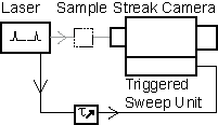
The Streak Principle

The streak principle is characterized by imaging an input slit on a screen while the image is swept in orthogonal direction with respect to the slit direction. The sweep is done with constant and well know speed. A temporal information can be related to the screen along the sweep direction and a spatial information can be related along the slit direction. Each point on the screen is therefore related to a time and spatial information. In case sweep speed is high compared to the duration of an optical pulse directed onto the input slit, the pulse is stretched in temporal direction. The length of the pulse on the screen can be related directly to its duration. The streak principle generates images with temporal information along one axis. The axis orthogonal to the temporal axis can stil be used to capture multiple signals as they are available for example on the output of a spectrometer.
 The streak principle can be realized by using a rotating mirror. Faster sweep speeds and therefore higher temporal resolution are achieved by using electron tubes, so called streak tubes. The input slit is focused onto the streak tube photocathode. Photoelectrons are emitted and accelerated onto the phosphor screen by high voltage. The image of the input slit appears on the screen. On the way from the photocathode to the screen, photoelectrons are passing deflection plates. A fast voltage transient is applied to deflect the electrons. A readout camera is used to capture the light from the phosphor screen. In many systems an additional amplification stage is needed. This might be an MCP inside the streak tube or an external image intensifier.
Trigger Configurations
The temporal resolution of streak camera systems is determined by the streak camera itself but also by the trigger configuration used to synchronize the camera to the optical signal. When selecting the trigger configuration, trigger delay and temporal relation between optical and electrical signals need to be considered. Therefore, the selection of light source or exciting laser system has to be completed priot to consider a particular trigger configuration. This description provides an overview of typical setups. Click here and ask for “AN-Trigger Configurations for Streak Cameras V2”.

MATLAB Support
The format used by OptoAnalyse to save image information is described. This article provides examples how these image data can be read by MATLAB or how TIFF files can be generated automatically be using MATLAB. The examples will simplify the access to streak images for further analysis. Click here and ask for “AN-MatLab Support”.
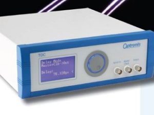
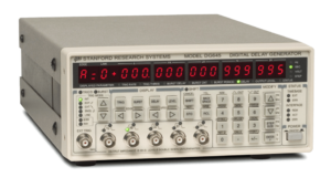 DG645
DG645
Use the delay and pulse generator DG645 (Stanford Research Systems) for systems with the TSU12-10, TSU21-10 and TSU22-10 sweep units. The DG645 is suitable for use with externally triggerable light sources.
 Datasheet
Possible Configurations for the SC-20 Streak Camera Range:
 SC-20/S25 with IOS-20 and TSU12-20/F1 as well as SI 1000
Temporal resolution: <600 ps (single-shot)
Timebase: 120 ns – 3 µs
Wavelength range: 350 nm – 950 nm
Trigger frequency: 0 – 10 kHz
Readout time: ~6 sec
Applications: Plasma physics, detonics
 SC-20/S25 with IOS-20/OV and TSU12-20 as well as SRU-BX/40
Temporal resolution: <1 ns (single-shot)
Timebase: 300 ns – 150 µs
Wavelength range: 350 nm – 950 nm
Trigger frequency: 0 – 10 Hz
Frame rate: 0 – 10 Hz
Applications: Plasma physics, detonics
For more information contact us here.